
Description of a Waterjet Cutting System
A Technical Guide to Waterjet Cutting
- Which Materials a Waterjet Can Cut
- How Does a Waterjet Cut?
- Characteristics of Waterjet Cutting
- Description of a Waterjet Cutting System
- Comparison Between Waterjet Configurations
- Comparison Between Waterjet Cutting and Other Cutting Methods
- Industries that Utilize Waterjet Cutting
- Environmental Impact of Waterjet Cutting
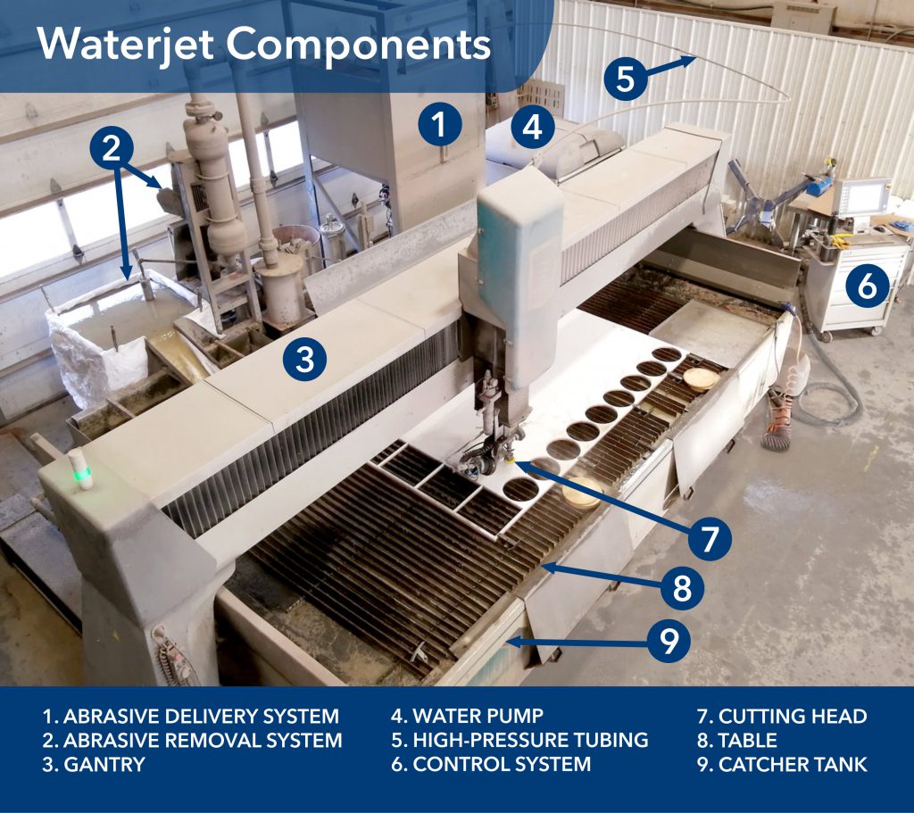
A waterjet cutting system requires a pump to pressurize the water, high-pressure tubing to carry the water, a piping system to deliver the abrasive, and a cutting head where the action happens. The movement of the cutting head is provided by a gantry, and a controller manages all of the components. A table is required to support the material, a tank of water is used to stop the stream, and an abrasive removal system disposes of the spent garnet.
Waterjet Pumps
Waterjet pumps produce an incredible amount of pressure. How do they do it? There are two main pump types, and we’ll look at them separately. For mid-range water pressures (50,000 to 60,000 psi), both direct drive pumps and intensifier pumps are common. For high water pressures (70,000 psi to 95,000 psi), only intensifier pumps can do it. Let’s consider both types.
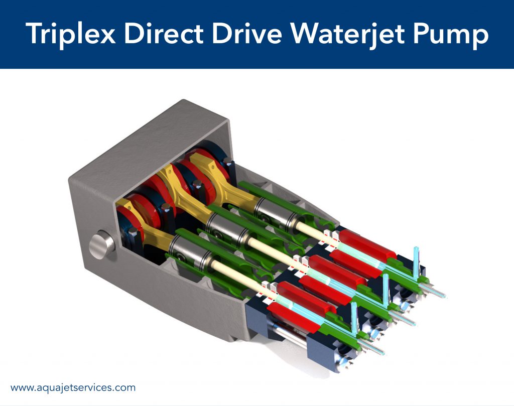
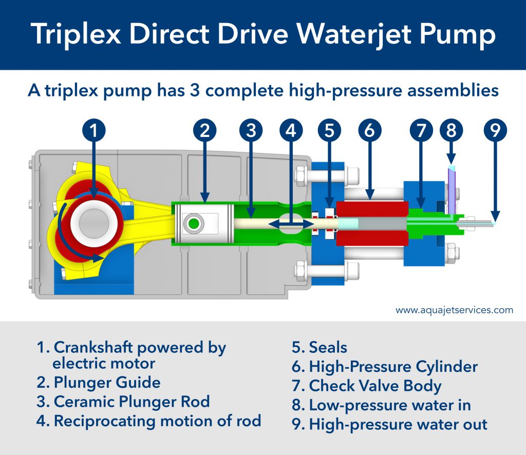
Direct Drive Pumps
Rotary direct drive pumps, also known as crankshaft pumps, produce water pressure in a manner that is similar to high-end pressure washer pumps—an electric motor-driven crankshaft powers 3 pistons that pump the water. This arrangement is called a triplex pump.
Direct drive pumps are inherently more efficient at turning electricity into water pressure, losing less energy in the form of wasted heat. However, direct drive pumps are limited to 60,000 psi, and their efficiency advantage disappears when comparing them to a 90,000 psi intensifier pump because cutting efficiency increases with pressure. Also, direct drive pumps cannot hold steady water pressure when the flow rate varies, preventing them from being used to run multiple cutting heads that are controlled independently. Finally, direct drive pumps have shorter maintenance intervals than intensifier pumps.
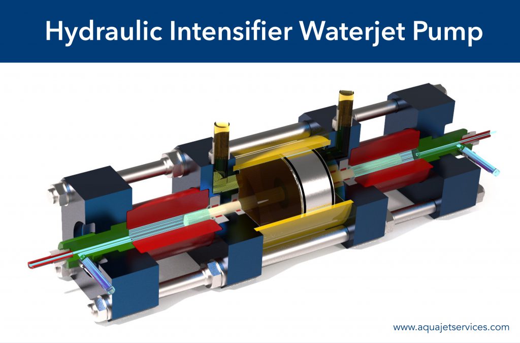
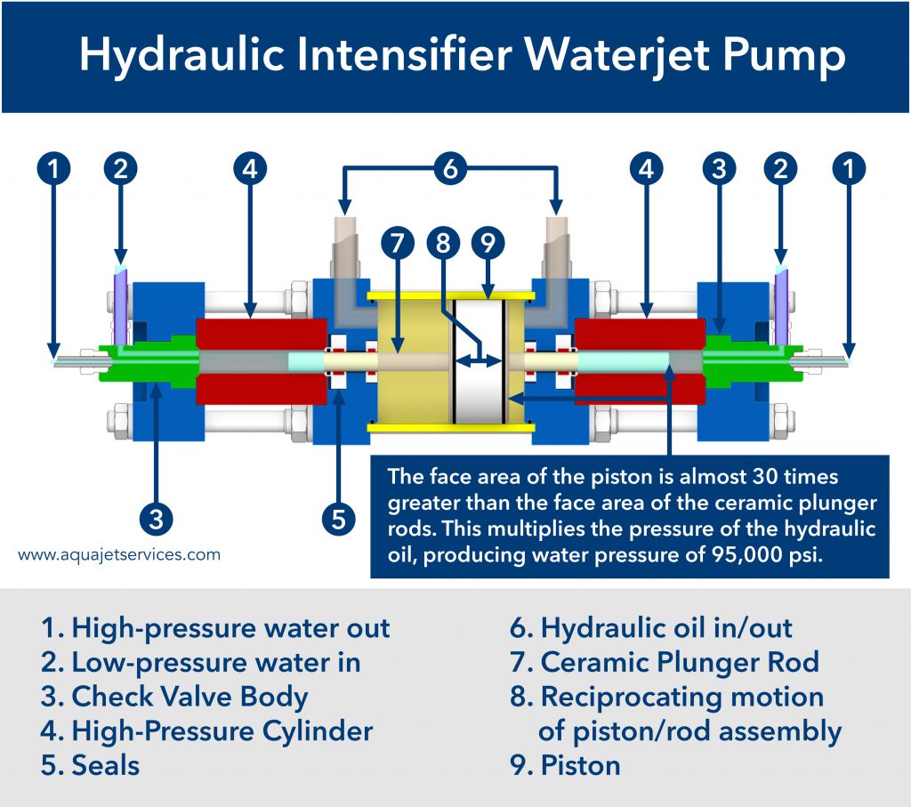
Intensifier Pumps
Linear intensifier pumps use big hydraulic pistons which apply their force to small ceramic rods that pressurize the water. Because the face area of the hydraulic piston is 20 to 30 times larger than the face area of the ceramic plunger, the plunger creates water pressure that is 20 to 30 times greater than the pressure of the hydraulic oil. This is called the intensification ratio. Obviously, the volume of the water to oil is the inverse of this ratio.
Intensifiers are the most commonly used type of waterjet pump because they have longer maintenance intervals than direct drive pumps, and they are capable of producing 95,000 psi. They also can hold steady water pressure despite varying flow rates, which is essential for operating multiple cutting heads with one pump.
Intensifier pumps are inherently less efficient at turning electricity into water pressure compared to direct drive pumps of the same pressure. However, this disadvantage disappears when comparing a 90,000 psi intensifier pump to a 60,000 psi direct drive pump because cutting efficiency increases with pressure. (For more information on the cutting performance of different pump types and, see Comparison Between Waterjet Configurations. )
High-Pressure Tubing
The stainless-steel piping must handle repeated pressure cycles up to 100,000 psi. To be strong enough to contain this pressure, the outer diameter of high-pressure tubing is about 3 times the inner diameter—a 3/8” OD tube will have an 1/8” ID. That means that the cross-sectional area of the bore is only 11% of the total area of the tube. But even with this strength, the tubing is gradually fatigued by pressurizing and depressurizing the tubing at such extreme levels.
To manufacture high-pressure tubing that can stand up to this pressure cycling, the autofrettage process is often used. In this process, the tube is pressurized past the yield strength of the inner bore, creating residual compressive stresses in the inner layers and residual tensile stresses in the outer layers. The tubing is enclosed in protective sheathing.
Are you imagining that a high-pressure tube blows up like a bomb when it fails? Nope, this tubing has been designed to fail safely. A tiny crack forms, and the water being forced out of the crack is heated to steam by friction. You just see a little plume of steam emanating from the tube at the location of the crack. When you turn off the pump and inspect the tube, you only find a tiny hourglass-shaped stress mark—the crack is too small to be seen without magnification.
But know that high-pressure tubing does fail and must be replaced. (Most tubing will last over 1,000 hours.) If down-time is not permissible, a set of spare parts for the high-pressure system must be kept on hand. When high-pressure tubing components fail, most of them can be replaced quickly and easily if the parts are on hand.
Abrasive Delivery System
The garnet abrasive is delivered to the cutting head by air pressure through a hose inside the gantry. The abrasive is supplied from a hopper that is pressurized to about 50 psi.
Cutting Head
Basic waterjets have a simple cutting head. The high-pressure water is controlled with an on/off valve above the orifice. The water passes through the orifice at supersonic speeds and enters the mixing chamber. The venturi effect of the high-velocity water stream draws in the abrasive, which is metered out at a prescribed flow rate from the abrasive delivery system.
The combined water/abrasive stream passes through the 1mm bore of a tungsten carbide mixing tube, also known as the waterjet nozzle, as the water accelerates the abrasive. The entire cutting head has to be carefully designed and assembled to ensure that the orifice is precisely aligned with the bore of the mixing tube. If anything is out of alignment, the water stream quickly destroys the mixing chamber and the tungsten carbide mixing tube. If you want to know more about what is going on inside a cutting head, see The Waterjet Stream.
A precise waterjet has a cutting head that is much more complex—it has a wrist with 2 axes of motion to control the angle of the stream. Some wrists are used only to compensate for taper in the cut. See Taper Compensation in Waterjet Cut. Other wrists can pivot up to 60° from vertical, enabling the waterjet to do 5-axis cuts. See 5-Axis Waterjet Cutting.
Gantry
To cut out parts, the cutting stream has to accurately draw their shapes. In the manufacturing world, the most common type of robot that draws on flat surfaces is the gantry. A gantry is a system in which a bridge moves along the length of its motion, and a carriage on that bridge moves across the width of its motion. Waterjet gantry areas range from smaller than an office desk to larger than a mobile home. In manufacturing, gantries are commonly used in waterjets, lasers, plasmas, routers, etc.
Basic waterjets draw in 2D by combining bridge motion with carriage motion. We call this 2-axis cutting, which involves the X-axis and the Y-axis. The XY drive system might be rack and pinion or ball nut and screw, but always powered by precise servomotors. There are also mid-range 3-axis waterjets—they have CNC-controlled movement in the vertical dimension as well, which is the Z-axis. Then there are top-of-the-line 5-axis waterjets that can also angle the stream with two rotational axes. Commonly, 5-axis waterjets are limited to rotating no more than 60° from vertical so that the operator doesn’t get hit with a blast of supersonic water.
A waterjet gantry must move very accurately—a good one can position the cutting head within 0.001” (0.025mm) of its intended location. That’s better than within 1 hair, if you like to talk hairs instead of inches. However, as the gantry maneuvers through the cutting path, the accelerations of the movement reduce the accuracy of the cutting head location. Waterjet gantries have to be very rigid to counteract the g-forces of their motion, so each gantry has an acceleration rating. Because a waterjet spends a lot of its time either slowing down or speeding up when cutting intricate geometry, the acceleration rating can be a big factor in the cut time.
So how much accuracy can a waterjet gantry achieve after we’ve thrown in these varying forces? A good waterjet gantry can do its cutting within 0.002” (0.080mm) of its intended motion, but there are some wrinkles we still haven’t mentioned. For the rest of this story, see Characteristics of Waterjet Cutting.
Control System
All of the above components are controlled by a computer that stands beside the waterjet and has a bunch of wires running to all of the controllers and motors and sensors. A machine like this is an impressive network of electronics. A waterjet computer uses CNC code, just like other cutting systems. As is to be expected, programming a waterjet has become much easier than it was in the good old days, and even 5-axis tool paths can be created quickly. However, good waterjet operators know that a computer can make a cut file, but it takes a brain to plan a cut that produces accurate parts.
Table and Catcher Tank
The waterjet table and catcher tank are one combination unit. The table consists of vertical steel slats that fixture the material. Plastic waterjet brick might be placed on top of the slats if fragile or small parts are being cut. All table components are gradually consumed as the waterjet stream repeatedly crosses them.
The water in the catcher tank is about 3 feet deep, and the water’s purpose is to disperse the cutting stream. The system is often designed so that the water level can be raised to submerge the table and the material being cut. This dampens the sound of the cutting and reduces spray from the cutting head.
Abrasive Removal System
As a waterjet cuts, the spent abrasive accumulates inside the tank. Many waterjets solved that problem with an abrasive removal system. This system uses a series of horizontal nozzles just above the floor of the tank to direct the water towards one end of the tank. This flow of water along the bottom carries the spent abrasive with it. Then the water and spent abrasive are pumped out and screened to remove any trash. From there it is pumped through a centrifuge to separate the abrasive from the water. The cleaned water is returned through the nozzles in the bottom of the tank, and the abrasive is released into a tank for disposal.